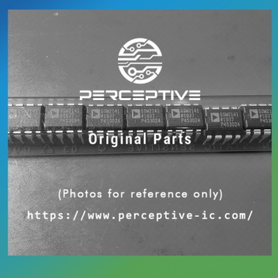
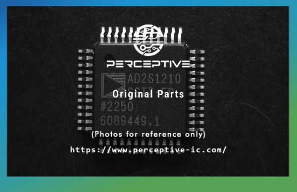
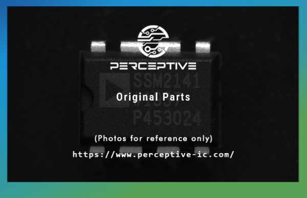
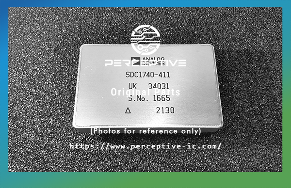
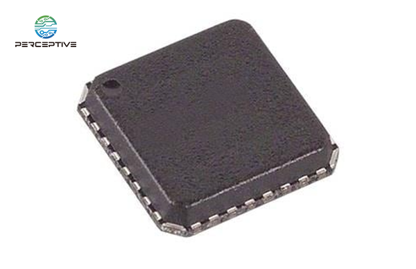
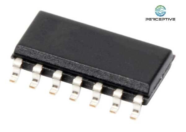
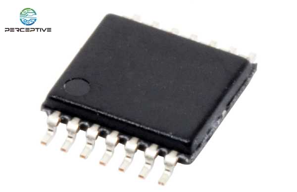
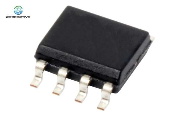
In electronic manufacturing, identifying component packaging accurately is just as important as selecting the correct electrical specification. Packaging affects how a component is mounted, how it performs under mechanical and thermal stress, and how smoothly it moves through the assembly line. Among the many package families, two remain the most commonly encountered: Surface-Mount Device (SMD) and Dual-In-Line Package (DIP). For procurement teams, engineers, and quality inspectors, being able to distinguish these packages quickly helps prevent sourcing errors, reduces rework, and ensures the right fit for the intended PCB design.
The world's largest supply platform for sources of shortages and hard-to-find parts
- Capacitors
- Resistors
- Linear
- Thyristors
-
Transistors
- Transistors - FETs, MOSFETs - Single
- Transistors - FETs, MOSFETs - RF
- Transistors - FETs, MOSFETs - Arrays
- Transistors - IGBTs - Modules
- Transistors - JFETs
- Transistors - IGBTs - Single
- Transistors - Bipolar (BJT) - Single
- Transistors - Bipolar (BJT) - Arrays
- Transistors - Bipolar (BJT) - Single, Pre-Biased
- Transistors - Bipolar (BJT) - RF
- Transistors - Bipolar (BJT) - Arrays, Pre-Biased
- Transistors - Special Purpose
- Clock/Timing
- Data Acquisition
-
Interface
- Interface - I/O Expanders
- Interface - UARTs
- Interface - Specialized
- Interface - Serializers, Deserializers
- Interface - Sensor and Detector Interfaces
- Interface - Sensor, Capacitive Touch
- Interface - Signal Terminators
- Interface - Signal Buffers, Repeaters, Splitters
- Interface - Modules
- Interface - Analog Switches - Special Purpose
- Interface - Analog Switches
- Interface - Filters - Active
- Interface - Telecom
- Interface - Direct Digital Synthesis (DDS)
- Interface - Encoders, Decoders, Converters
- Interface - CODECs
- Interface - Voice Record and Playback
- Interface - Modems - ICs and Modules
- Interface - Drivers, Receivers, Transceivers
-
Embedded
- Embedded - DSP (Digital Signal Processors)
- Embedded - FPGAs (Field Programmable Gate Array)
- Embedded - PLDs (Programmable Logic Device)
- Embedded - FPGAs with Microcontrollers
- Embedded - Microprocessors
- Embedded - Microcontrollers - Application Specific
- Embedded - Microcontrollers
- Embedded - System On Chip (SoC)
- Memory
- Isolators
- Diodes
-
PMIC
- PMIC - AC DC Converters, Offline Switchers
- PMIC - LED Drivers
- PMIC - OR Controllers, Ideal Diodes
- PMIC - PFC (Power Factor Correction)
- PMIC - RMS to DC Converters
- PMIC - V/F and F/V Converters
- PMIC - Power Over Ethernet (PoE) Controllers
- PMIC - Full, Half-Bridge Drivers
- PMIC - Display Drivers
- PMIC - Gate Drivers
- PMIC - Laser Drivers
- PMIC - Hot Swap Controllers
- PMIC - Thermal Management
- PMIC - Lighting, Ballast Controllers
- PMIC - Voltage Reference
- PMIC - Motor Drivers, Controllers
- PMIC - Battery Chargers
- PMIC - Battery Management
- PMIC - Current Regulation/Management
- PMIC - Power Supply Controllers, Monitors
- PMIC - Power Management - Specialized
- PMIC - DC DC Switching Controllers
- PMIC - DC DC Switching Regulators
- PMIC - Voltage Regulators - Special Purpose
- PMIC - Voltage Regulators - Linear
- PMIC - Voltage Regulators - Linear + Switching
- PMIC - Linear Regulator Controllers
- PMIC - Energy Metering
- PMIC - Power Distribution Switches, Load Drivers
- PMIC - Power Driver Modules
- PMIC - DC-DC Converter
-
Sensors, Transducers
- Specialized Sensors
- Angle, Linear Position Measuring
- Optical Sensors - Photo Detectors - Logic Output
- Optical Sensors - Photodiodes
- Optical Sensors - Phototransistors
- Photointerrupters - Transistor Output
- Photointerrupters - Logic Output
- Optical Sensors - Reflective - Analog Output
- Optical Sensors - Reflective - Logic Output
- Optical Sensors - Distance Measuring
- Optical Sensors - Ambient Light, IR, UV Sensors
- Pressure Sensors, Transducers
- Optical Sensors - Image Sensors, Camera
- Multifunction
- Proximity Sensors
- Amplifiers
- Gas Sensors
- Flow Sensors - Industrial
- Flow Sensors
- Float, Level Sensors
- Temperature Sensors - RTD
- Temperature Sensors - Analog and Digital Output
- Temperature Sensors - Thermostats - Solid State
- Thermocouples, Temperature Probes
- Humidity, Moisture Sensors
- Current Sensors
- Position, Proximity, Speed (Modules) - Industrial
- Position, Proximity, Speed (Modules)
- Magnetic Sensors - Switches (Solid State)
- Magnetic Sensors - Linear, Compass (ICs)
- Compass, Magnetic Field (Modules)
- Encoders
- Motion Sensors - IMUs (Inertial Measurement Units)
- Motion Sensors - Inclinometers
- Motion Sensors - Optical
- Motion Sensors - Accelerometers
- Motion Sensors - Vibration
- Motion Sensors - Gyroscopes
- Connectors, Interconnects
- Integrated Circuits
- Optoelectronics