1. Introduction to LM386 Audio Amplifier IC
The LM386 is an audio power amplifier integrated circuit designed for low voltage consumer applications. Ideal for battery-operated devices such as radios, doorbells, phones, guitar amps, and hobby electronics projects. It is primarily used as an amplifier in computer speakers and small portable stereo systems.
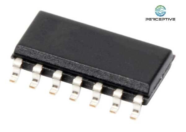
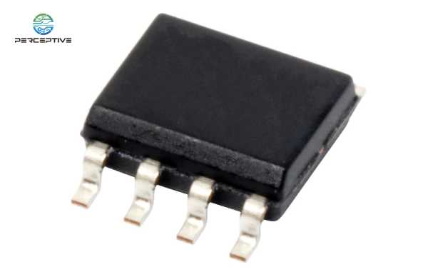
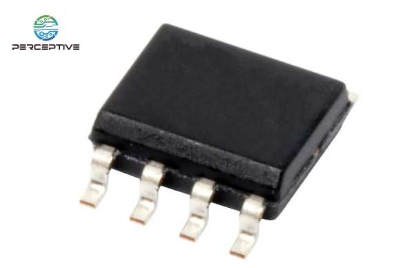
The LM386 is available in an 8-pin dual in-line package (DIP-8). The voltage gain of the amplifier can be adjusted to 20, and can be increased to 200 by adding external components such as resistors and capacitors between pin 1 and pin 8. The LM386 amplifier consists of 8 pins, of which pins 1 and 8 are gain control pins. This allows the client to control the volume. Depending on the model, the amplifier can deliver output power in the range of 0.25W to 1W from a 9 volt supply.
2. Features and Specifications of the LM386
Wide supply voltage range: 4V-12V or 5V-18V (based on model)
Voltage Gain from 20 to 200
battery operated
Minimal External Components
Low Static Power Consumption: 4mA
Available in MSOP package
Working temperature: 0-70˚C
Low distortion: 0.2%
Input is referenced to ground
Self-concentric output quiescent voltage
Speaker impedance 4Ω
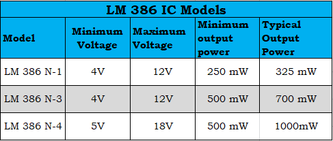
Electrical Characteristics of LM386
Depending on the model, the voltage gain of the LM386 amplifier can vary from 20 to 200 with a supply voltage range of 4V-12V or 5V-18V. There are three types of audio power amplifiers on the market: LM386N-1, LM386N-3, and LM386N-4.
The table below gives the minimum voltage, maximum voltage, minimum output power and typical output power of the amplifiers associated with these three models.
3. LM386 Pin Configuration
The physical diagram and pin configuration of the LM386 are shown in the figure below. LM386 has a total of eight pins, each with different functions.
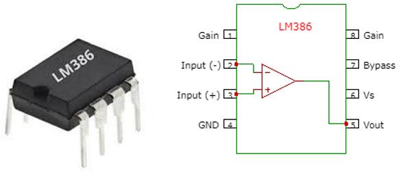
Pin Description
Pin1 (Gain) : This is a gain pin to adjust the amplifier gain by connecting this IC to an external component capacitor.
Pin 2 (Input -) : Non-inverting input terminal, used to provide audio signal.
Pin 3 (Input +) : Inverting input terminal, used to provide audio signal.
Pin 4 (GND) : It is the ground pin, connected to the ground of the system
Pin 5 (Vout) : An output pin used to provide amplified output audio, associated with a speaker.
Pin 6 (Vs) : Connect to power supply and receive positive DC voltage.
Pin 7 (Bypass) : This is a bypass pin for connecting a decoupling capacitor.
From this pin description, you can see
Pin 1 and pin 8 represent the gain control end of the amplifier. These are the terminals where we can adjust the gain by placing a resistor and capacitor or just a capacitor between these terminals.
Pin 2 and Pin 3 represent sound input signal terminals. These are the terminals where we place the sound we want to amplify. Pin 2 is the negative input and pin 3 is the positive input.
Pin 4 is the GND (ground) terminal, which is grounded in the circuit.
Pin 5 represents the output of the amplifier. An amplified signal comes out of this terminal.
Pin 6 receives a positive DC voltage so that the amplifier can receive the necessary power to amplify the signal.
Pin 7 represents the bypass terminal. This terminal can be bypassed with a 15KΩ resistor. It is usually suspended or grounded in circuit design. However, for better stability, a capacitor can be added to the circuit to prevent the op amp IC from oscillating.
4. LM386 circuit diagram and working
Basically, the audio amplifier LM386 consists of three functional blocks, which are: power supply and output, bypass and gain control. The audio amplifier circuit diagram using LM386 is shown in the figure below.
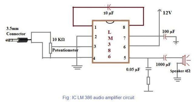
The main components of the audio amplifier are LM386, power supply - 12V, capacitors such as 100µF, 1000µF, 0.05µF, 10µF, potentiometer - 10KΩ, connector, resistor - 10KΩ, speaker - 4Ω. These components are connected according to the circuit diagram above.
For the design of this audio amplifier, first connect the two power supply pins (pin 4 and pin 6), where pin 4 is connected to ground and pin 6 is connected to the 12V power supply. Once powered, connect the input from any type of audio source such as a phone or microphone via the 3.5mm connector. The LM 386 uses a source connection with a ground terminal for left and right audio.
A potentiometer is connected to the input to control the input level in the circuit. Additionally, a capacitor can be connected in series to the input to remove the DC component.
The IC is adjusted for a gain of 20, which can be increased to 200 by connecting a capacitor (10µF) between pin 1 and pin 8. We can make a bypass capacitor to reduce noise by connecting a capacitor (100µF) at pin 7 of the LM386 IC.
At the output connection, a capacitor (0.05 µF) and a resistor (10 Ω) are connected in series between GND, which is connected to pin 5 of the IC. The circuit forms a Zobel network, a filter circuit with capacitors and resistors to adjust the input impedance.
With impedance, speakers can be connected in the range of 4 Ω to 32 Ω. Here, the audio amplification circuit uses a speaker (4Ω). The speaker can be connected to a capacitor (1000 µF) to remove unwanted DC components from the signal.
How to control the gain of LM386?
The LM386 is designed in such a way that pins 1 and 8 have gain controls that can be set externally. An internal resistor (1.35KΩ) sets the IC's gain to 20 when the CONTROL pin is left floating. If you add a capacitor across the CONTROL pin, the gain will increase to 200.
Therefore, the gain of the LM386 can be adjusted simply by connecting a potentiometer in series with a capacitor between pin 1 and pin 8.
5. Application of LM386 Audio Amplifier IC
The audio amplifier LM386 can be used in a variety of applications. It is one of the most important ICs in the audio section and is often used in the following applications:
Battery powered systems such as TV sound systems, ultrasonic drivers, microphone recording
AM and FM radio amplifiers
low power audio amplifier
portable music player
Laptop/computer speakers and small portable speakers
audio booster
Wien Bridge Oscillator
walkie talkie
power converter
If you need products, please send us BOM at any time!