Overview
In this article, a LED Chaser circuit will be made using 555 Timer IC and CD4017. An LED chaser is an electronic circuit that creates visually appealing effects by sequentially lighting multiple LEDs in a repeating pattern. This creates the illusion of a "chase" or "light chase" effect as the lit LEDs appear to move in the array. LED follow spots are popular in a variety of applications such as decoration, signage, display panels and holiday lighting.
This can be achieved using 555 timer IC, CD4017 decade counter IC.The 555 timer generates clock pulses, and the CD4017 divides the input frequency to drive the LEDs in turn. Here is an easy way to build a LED Tracker circuit using 555 Timer IC and CD4017 Decade Counter IC.
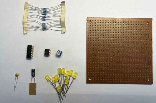
Required components
555 timer IC
CD4017 decade counter IC
LEDs – 10
10kΩ resistor - 1
220Ω resistor - 10
10kΩ potentiometer - 1
10µF capacitor
10nF capacitor
Breadboard or PCB
Jumper
9V battery or power supply
Circuit and printed circuit board design
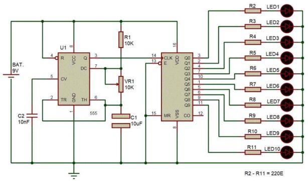
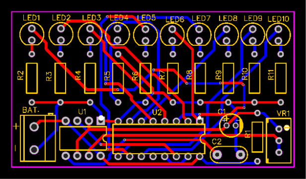
Following is the LED Chaser circuit designed using 555 Timer IC and CD4017 Decade Counter IC.
The PCB for this project was designed with EasyEDA software.
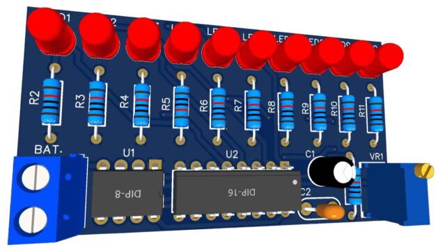
Here's a 3D view of the PCB that looks great.
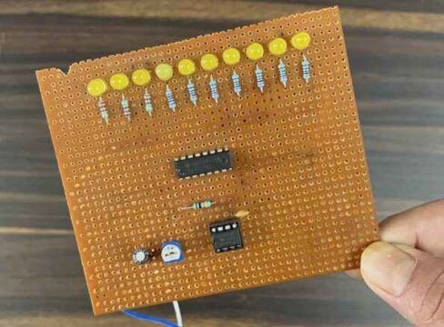
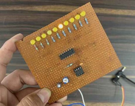
For testing purposes, a Vero Board was used and all components were assembled to power the circuit from a 12V battery.
LED Chaser circuit work based on 555 timer and CD4017
After the circuit is completed, turn on the power to see the LEDs glow one by one. By changing the values of resistors and capacitors in the 555 timer IC circuit, the speed of the chasing effect can be adjusted. For example, you can experiment with different resistor and capacitor values to find the chase speed that suits your preference.
In this LED Chaser Circuit project, a 555 timer is set up as an Astable multivibrator with both signal phases unstable and it is used as a frequency generator. The output signal from Astable is used to trigger the CD4017 counter IC to change state and perform the desired action.
The 555 timer IC is connected in Astable mode to generate a trigger pulse for a specific time period. A variable resistor for the output frequency is included to adjust the 555 timer. A CD4017 counter IC is also included in the circuit used to control the LEDs. Ten LEDs are connected to the Q0-Q9 pins (pin 3) through 220 ohm resistors. The MR pin (pin 15) and the enable or clock disable pin (pin 13) are directly connected to ground, while the clock pin of the counter is directly connected to the output pin of the 555 timer.
If interested, please feel free to contact us via BOM!