First. Solution Description
In the traditional automotive architecture, the system uses a distributed automotive electronic and electrical architecture (EEA), and the ECUs in the vehicle are connected together via CAN or LIN bus. With the increase of people's requirements for the safety, efficiency, and comfort of automobiles, the degree of electronicization of vehicles has developed rapidly, and the number of ECUs on cars has grown rapidly. There are basically dozens of ECUs on cars, and some have even reached the top. Hundreds, the distributed architecture has been challenged. The large number of ECU units has led to a significant increase in the complexity of electronic software development, and developers have begun to pursue a modular, portable, and easy-to-manage architecture.
In order to meet the needs of modern automobiles, the concept of domains has been proposed. The automobile is divided into multiple domains for management to form an automotive network architecture. It is mainly divided into the body domain, power domain, chassis domain, ADAS domain, external network domain, and infotainment domain. The communication between different domains has become an important function, which is the concept of the domain controller DCU (Domain Control Uint). .
When the current domain exchanges information and communicates with other domains, the domain controller becomes a bridge for external communication. Therefore, the domain controller kernel needs strong hardware computing capabilities, and the security of message exchange is more important. The rich communication interface makes the exchange of bus messages easy. NXP MPC5744P is a dual-core Lockstep PowerPC e200z4 core with a main frequency of 200MHz and an ISO-26262 ASIL-D rating for automotive functional safety.
Second, the design hardware design architecture
Choice of main platform
The main platform of this vehicle domain controller application solution is NXP MPC5744P, which has a main frequency of 200MHz and abundant peripheral resources. The reason for using this platform is that ASIL D's functional safety level and abundant peripheral resources can facilitate later vehicle functions. Expansion and update of security levels and peripheral peripherals.
Main features of the platform:
Two e200z4 cores with delayed lockstep, operating up to 200 MHz
Designed for functional safety (ISO 26262 / ASIL-D)
5 MB Flash, 384 KB SRAM
3 FlexCAN, 2 LINFlexD, 4 DSPI, 4 SENT, support for LFAST SIPI, dual-channel FlexRay ™ controller, 10 / 100M Ethernet
Power design
FS8510 chip design, ASIL D functional safety level, can provide 1 VPRE (10A), 3 BUCK (3.6A), 2 LDO (400mA) and BOOST features, providing a rich peripheral configurable power resources And functional safety ASIL D level, providing the possibility for later hardware to improve the functional safety level.
Other peripherals
Using TJA1105, TJA1101, TJA1021T / 3, TJA1081, TJA1042, TCAN4550 etc. chip design, with a variety of automotive communication features, providing LIN, CAN 2.0 A / B, RAY, ENET, Zipeire, CAN FD etc. Communication function to provide hardware support for later automotive network bus upgrades.
Scene application diagram

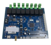
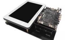
Display board photos


Solution block diagram

PCB Layout Design

Core technology advantages
Main core frequency 200MHz
Support Zipwire communication function
Support vehicle Ethernet to communicate with external devices
Support 100Base-TX Ethernet communication through RJ45 interface
Support LIN and FlexRay communication
Can control OLED screen to display text or image
Support communication using OBD interface
Supports 3 CAN and 1 CAN FD functions
MPC5744P and FS8510 functional safety ISO-26262 ASIL D grade
Monitor and control power and MCU status through PMIC FS8510
Solution specifications
1. The board uses a domain controller system with MPC5744P as the main system control chip and FS8510 as the main power control chip.
2. Motherboard size: 135.0mm x 185.0mm.
3. Rich CAN, LIN, RAY, ENET, Zipwire and Ethernet interfaces.
4. Provide power for the entire domain controller and monitor MPC5744P through PMIC FS8510, and report the data related to the detected power to the MCU.


