When a finished electronic device starts malfunctioning, the fastest path to a solution is not swapping parts at random—it's following a systematic troubleshooting process. A disciplined, evidence-driven approach helps you isolate the real cause—whether it's a defective component, a soldering issue, or a handling error—and avoid unnecessary replacements.
1) Define the Symptom Clearly
Start by documenting what fails, when it happens, and under which conditions—temperature, load, voltage, or environmental factors. Record firmware versions, BOM revisions, lot/date codes, and storage history. Include customer feedback if it's a returned unit, as end-user observations can reveal environmental factors not present in the lab. Many issues initially blamed on components are actually caused by process escapes that appear only under specific scenarios.
2) Break Down by Subsystem—Power and I/O First
Most product failures trace back to power integrity or connectivity problems.
Power path: Verify voltage rails in sequence, check inrush current, and compare against a known-good unit. Look for ripple, voltage sag, or overcurrent shutdowns.
Interconnects: Cold solder joints, cracked traces under BGAs, or marginal connectors often cause intermittent faults.
Use boundary-scan testing to check connectivity without probing every point, and automated X-ray inspection (AXI) to find hidden solder defects such as opens, voids, or misalignments. If available, power integrity analysis tools can detect droops or noise that trigger failures under load.
3) Use a Rapid Isolation Toolkit
A/B module swaps: Swap entire functional blocks—display, RF front-end, battery—before removing individual components.
Thermal scans: Identify abnormally hot or cold components during operation.
Non-destructive imaging:
AXI (2D/3D X-ray) for BGA/QFN solder quality.
C-SAM acoustic microscopy to detect internal package delamination caused by moisture or reflow stress.
Dye-and-pry analysis: As a last resort, this method reveals micro-fractures in hidden solder joints.
A good practice is to maintain a small library of “golden” reference boards for quick side-by-side comparisons—both visually and electrically.
4) Verify Against Process Standards Before Blaming the Component
Before you attribute the problem to the component itself, check workmanship against IPC-A-610 soldering quality criteria. Many “component failures” are actually solder defects, contamination, or mechanical stress.
Also confirm handling compliance with J-STD-033 moisture-sensitivity guidelines—improper baking or exceeded floor life can crack IC packages and cause latent failures. For high-reliability products, adding a moisture indicator card to every moisture-sensitive device bag can help track exposure at a glance.
5) Common Real-World Culprits and Quick Checks
MLCC shorts: Measure resistance from power rail to ground; even a single failed capacitor can pull down an entire system.
ESD/EOS damage: Look for abnormal quiescent current, latch-up behavior, or temperature-dependent failures.
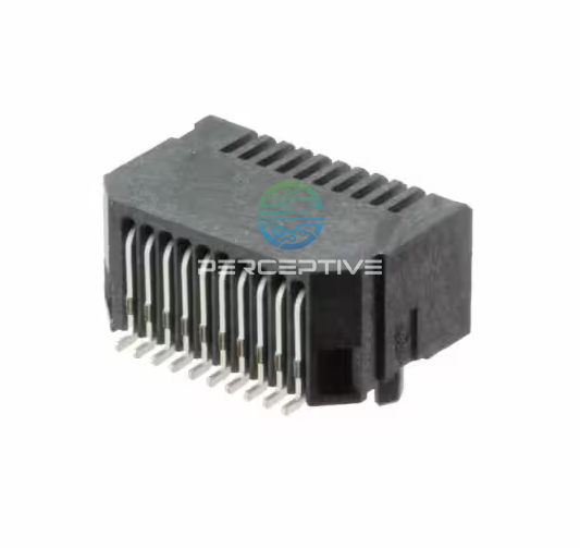
Connector issues: Check for oxidation, misalignment, or loose insertion—especially on flex cables that experience vibration.
Crystal oscillators: Test startup waveforms and drive levels under temperature extremes; a sluggish start can cause boot failures.
Firmware mismatches: Ensure the correct configuration or NVM image is loaded; a mismatched build can make healthy hardware appear faulty.
6) Rule Out Counterfeit or Misrepresented Parts
Open-market procurement can introduce risk. Follow AS5553 counterfeit mitigation standards, and verify authenticity with traceability to the original component manufacturer (OCM). Inconsistent performance across identical builds or unexplained lot-to-lot variation may indicate suspect parts. Where possible, request manufacturer-provided electrical characterization data for the lot in question.
7) What Perceptive Components Can Provide to Support Your Investigation
When you work with Perceptive, you gain access to:
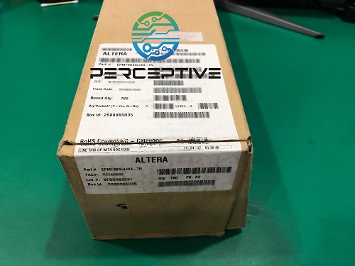
Full lot traceability and Certificates of Conformance from authorized sources.
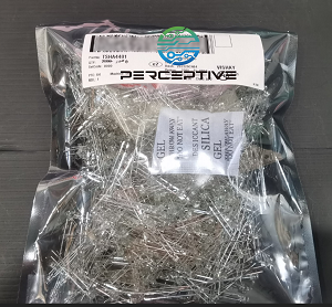
Moisture-sensitive labeling and storage records to confirm compliance with J-STD-033.
Incoming and advanced screening options: boundary-scan testing, AXI imaging, and C-SAM package inspection.
Failure analysis support with a step-by-step evidence chain—from visual inspection to advanced imaging—ensuring accurate root-cause identification.
Proactive screening programs for high-reliability customers to detect latent defects before assembly.
8) A Simple Workflow You Can Adopt
Reproduce the failure with controlled conditions, logging all variables.
Isolate by subsystem (power → I/O → clocks/RF → sensors).
Screen with boundary-scan and AXI; use C-SAM if package integrity is in doubt.
Verify process compliance with IPC-A-610 and J-STD-033.
Engage failure analysis for root cause and counterfeit screening if needed.
Document findings in a shared knowledge base to prevent recurrence in future builds.
Conclusion
Pinpointing the faulty component in a finished product requires a methodical approach that combines design knowledge, inspection technology, and process verification. At Perceptive, we help customers shorten this journey by offering traceable sourcing, advanced screening, and professional failure analysis—so you can solve issues faster, protect product reliability, and avoid unnecessary replacements. Our goal is not just to identify the failing part, but to strengthen your supply chain against repeat issues in the future.

