1. Introduction: L298 Dual H-Bridge Motor Driver IC
With high voltage and high current, the L298 IC is a dual H-bridge motor driver designed to accept standard TTL logic levels (control logic) to control different inductive loads such as DC motors, relays, solenoids, stepper motor etc. It is a high power version of the L293 motor driver IC.
The L298 can be used to control the direction of rotation of a DC motor. Four independent power amplifiers are included in the L298 IC. Two amplifiers can form H-bridge A, and two other amplifiers can form H-bridge B. Here, one H-bridge is used for polarity switching to control the direction of the motor, while a pair of H-bridges are used to control the bipolar stepper motors.
In the L298 IC, two enable inputs are provided to enable or disable the device independently of the input signal. All enable and input pins are used with 5V TTL logic to simplify interfacing with different types of microcontrollers. These enable pins can be used to activate all outputs simultaneously.
2. L298 Features and Specifications
Operating Supply Voltage Up to 46V (+5V to +46V Range)
Up to 4 A total DC current (2A per channel)
Logic input voltage up to 1.5 V
high noise immunity
TTL control input
25W power consumption
low saturation voltage
over temperature protection
Operating temperature range is -23°c to –130°c
Storage temperature range is -40°c – 150°c
3. L298 pin configuration and description
L298 IC is a 15-pin IC.
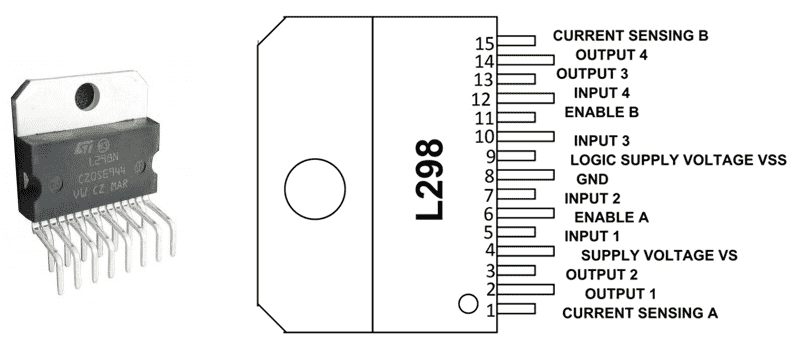
The IC includes dual bridges, H-bridge A and H-bridge B. The following is the function introduction of each pin of L298 IC.
Pin1 (Current Sense A): Used to control the flow of load current
Pin2 (Output 1): It is the output pin of H-bridge A, the current flows through the load and is monitored at pin 1.
Pin 3 (Output 2): is the output pin of H-Bridge A, the current flows through the load and is monitored at pin 1.
Pin4 (VS): It is the voltage supply pin, connected to +5V power supply.
Pin5 (input 1): is the input of control bridge A and is TTL compatible.
Pin6 (Enable A): is a TTL compatible enable input. Low state for people with disabilities.
Pin7 (input 2): is the input of control bridge A and is TTL compatible.
Pin8 (GND): It is the ground pin.
Pin9 (logic power supply voltage Vss): It is the logic block that provides the power supply voltage.
Pin10 (Inputs3): is the input to control bridge B and is TTL compatible
Pin11 (Enable B): is a TTL compatible enable input.
Pin12 (Inputs4): is the input to control bridge B and is TTL compatible
Pin 13 (Output 3): where the current through the load is monitored at pin 15, is the output pin of the H-bridge B,
Pin 14 (Output 4): Where the current through the load is monitored at pin 15, is the output pin of the H-bridge B.
Pin 15 (Current Sense B): Used to control the flow of load current
4. L298 application
The L298 dual H-bridge motor driver IC has a variety of applications. It is usually used to control the direction of the motor as well as the speed of the motor. It is suitable for different fields such as robotics, embedded, etc. The following are a few areas where the L298 IC is applicable.
It is used in applications requiring high power motor drives. Since microcontrollers operate at very low voltage and current, the L293 motor IC is the first choice for high voltage and current applications.
It is basically used in applications using H bridges. That is in H-bridge based applications.
Suitable for applications requiring current control and PWM operable ICs.
Suitable for occasions where the control unit can only provide TTL output.
It is also suitable for many real-life applications such as relay drivers, robotics, automatic door control systems, weight lifters, etc.
Similar models:
If you need this product, please contact us through BOM!