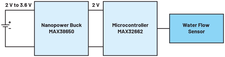
Battery-powered circuits must be energy efficient so that the battery can continue to supply power for a long period of time. For this reason, energy-efficient components should be selected and integrated into the system. The fewer building blocks in the circuit, the more energy efficient the overall system will be. The water meter shown in Figure 1 is a battery-powered device. The system utilizes a MAX32662 microcontroller with only one supply voltage. The input voltage is between 1.71 V and 3.63 V.
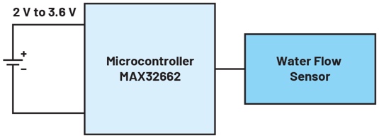
The microcontroller can be powered directly from the battery, which provides 2 V to 3.6 V depending on temperature and state of charge. Very few additional components are required in the circuit, so very high overall system efficiency can be achieved. However, the current consumptions of the microcontroller are largely irrelevant to the actual supply voltage. Whether the microcontroller operates at 2 V or 3.6 V has no effect on this IC.
For cases like this, the new nanopower switching regulators can be used. These switching regulators can efficiently convert the battery voltage to a lower value, e.g. 2 V. The nanopower switching regulator provides the required current to the microcontroller at the output, but the higher the voltage on the battery side, the lower the current required. Figure 2 shows the water meter circuit with the addition of the highly efficient nanopower switching regulator MAX38650.
Adding this IC significantly extends battery life. Battery life can easily be extended by 20% or more. The exact energy savings vary from case to case due to the many influencing parameters, such as temperature, peak current, cyclic shutdown of sensors etc. The decisive factor here is the quiescent current of the added DC-DC converter. If the switching regulator's energy consumption is too high, the expected energy-saving gains are lost.
Figure 3 shows a circuit with a MAX38650 nanopower regulator. As the name implies, the IC has a nano-amp quiescent current. During operation, the switching regulator draws only 390 nA of quiescent current. When the DC-DC converter can be turned off, it requires only 5 nA of shutdown current. This nanopower voltage converter is ideally suited to achieve energy savings in systems like the one shown in Figure 1.
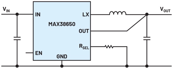
As shown in Figure 3, the circuit requires only a few passive external components. Only one resistor on the RSEL pin is used to set the output voltage, and no resistive voltage divider is used. A resistive voltage divider draws a considerable amount of current, which, depending on the voltage and resistance, can greatly exceed the quiescent current of the MAX38650. Therefore, the IC uses a variable resistor and checks this resistor only briefly when the circuit is turned on. The IC checks the value of the setpoint output voltage by flowing a current of 200 µA through the variable resistor for a short time during the turn-on period. The resulting voltage is then measured and stored inside the IC. This means that no energy is lost during operation through a conventional voltage divider.
By adding a voltage converter, system efficiency can be improved and battery life extended.
For more exciting articles, please click perceptive-ic.com.