Linear regulators can be considered a low-noise solution when minimizing EMI (electromagnetic interference) is a priority in the design, but they are not suitable for this scenario due to heat dissipation and efficiency requirements. switching regulator. Even in EMI-sensitive applications, the switching regulator is often the first active component on the input power bus, which can significantly affect the EMI performance of the entire converter regardless of the downstream converter. So far, there is no clear way to ensure that EMI can be suppressed and efficiency requirements can be met through the selection of power ICs. The LT8614 Silent Switcher™ regulator now does just that.
Compared with current advanced switching regulators, LT8614 can reduce EMI by more than 20dB. In contrast, it reduces EMI by a factor of 10 at frequencies above 30MHz without compromising minimum turn-on, turn-off times or efficiency in equivalent board area. It does this without additional components or shielding and represents a major breakthrough in switching regulator design.
A New Solution to Improve EMI Problems
A surefire way to solve EMI (Electromagnetic Interference) problems is to use a shielded box for the entire circuit. Of course, this significantly increases the required board space, component and assembly costs, while increasing the complexity of thermal management and testing. Another way is to slow down the edge of the switch. However, this has undesirable effects such as reduced efficiency, increased minimum on and off times and their associated dead times, and affects the potential potential current control loop speed.
The LT8614 Silent Switcher regulator achieves the desired effect without using a shield box (see Figure 1). With an IQ as low as 2.5µA, the LT8614 draws a total supply current of 2.5µA when regulating with no load, which is important for always-on systems.
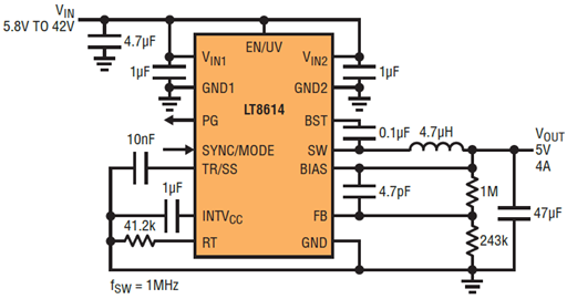
Figure 1. The LT8614 Silent Switcher minimizes EMI/EMC emissions while achieving high efficiency (switching) at frequencies up to 3MHz.
Its ultra-low dropout is limited only by the internal top switch. Unlike other solutions, the LT8614's VIN-VOUT (input output voltage) limitation is not limited by the maximum duty cycle and minimum off-time.
Meanwhile, the typical minimum operating input voltage is only 2.9V (3.4V maximum), enabling it to supply 3.3V in the buck state. Due to the LT8614's lower total switch resistance, its efficiency is higher than competing devices at high currents.
The LT8614 can be synchronized to an external operating frequency from 200kHz to 3MHz. Due to the low AC switching losses, it can operate with minimum losses at high switching frequencies. A good balance is achieved in EMI-sensitive applications such as those common in many automotive environments, and the LT8614 can operate below the AM band for lower EMI, or above the AM band. In a setup with a 700kHz operating switching frequency, the standard LT8614 demo board does not exceed the noise floor in CISPR25 Class 5 measurements.
In conclusion
As we all know, in order to pass the electromagnetic interference test when the system design is completed, the electromagnetic interference problem needs to be carefully considered in the initial design stage of the converter. The LT8614 Silent Switcher regulator can ensure successful and feasible implementation of this requirement by selecting the power IC. The LT8614 reduces EMI generated by current state-of-the-art switching regulators by more than 20dB, and does not require additional components or additional shielding even with improved conversion efficiency.
Switching Regulators and EMI
The layout design of the printed circuit board determines the function, electromagnetic interference and thermal behavior of a power supply and determines the success or failure of every power supply design. While switching power supply layout is not a magic trick, it is often overlooked during the initial design process. Since functional and EMI requirements have to be met, factors that favor the functional stability of a power supply generally also favor EMI emissions. Know that having a good layout from the start not only adds no cost, it actually saves cost and eliminates the need to change EMI filters, mechanical shielding, EMI test time, and PC boards.
There are two types of EMI emissions: conducted and radiated. Conducted emissions are connected to the product through wires and traces. Since this noise is localized to specific terminals or connectors in the design, good layout and filter design can often ensure conducted emissions compliance early in the development process.
Radiation emissions, however, are another story. Anything on a circuit board that carries current radiates an electromagnetic field. Every trace on the board is an antenna, and every copper layer is a mirror. Anything other than a pure sine wave or DC voltage will produce a broad signal spectrum. Even with careful design, developers can't really know how severe the radiation emissions will be until the system is tested. Radiated emission testing can only be formally performed after the design is basically completed.
Filters typically reduce EMI by attenuating signal strength at a certain frequency or within a certain frequency range. By adding a metal plate as a magnetic shield, a portion of the energy in space (radiation) can be attenuated. Suppress the energy in the low frequency portion of the PCB trace (conducted) by adding ferrite beads and other filters. EMI cannot be eliminated, but it can be attenuated to a level acceptable to other communications and digital devices. Additionally, some regulators ensure compliance by implementing relevant standards.
Modern input filters using surface mount technology have better performance than through-hole devices. However, this improvement cannot keep pace with the increase in operating frequency of switching regulators. Higher efficiency, shorter turn-on and turn-off times, and faster switching transitions result in higher harmonic content. EMI worsens by 6dB for every doubling of the switching frequency, keeping all other parameters (such as switching capacitance and transition time) constant. If the switching frequency is increased by a factor of 10, the broadband EMI performance will be like a first-order high-pass filter, and the radiation will increase by 20dB.
A savvy PCB designer will keep the hot loop small and keep the shield ground plane as close as possible to the active layer. Nonetheless, the device pinout, package construction, thermal design requirements, and package size required to store sufficient energy in decoupling components all dictate that thermal loops be minimized. Adding to the complexity in typical planar PCB designs, magnetic or transformer-like coupling between traces above 30 MHz weakens any filter since poor magnetic or antenna coupling becomes more pronounced at higher frequencies role.
Potential interference and noise issues can become more severe when multiple DC/DC switch mode regulators are connected in parallel for current sharing and higher output power. If all the regulators were operating (switching) at a similar frequency, then the combined energy generated by the multiple regulators in the circuit would be concentrated at that frequency and its harmonics. , the presence of this energy can become a difficult problem for other ICs on PC boards and other system boards, where devices are in close proximity and susceptible to this radiated energy. This is a particular concern in automotive systems, where components are dense and often located in close proximity to audio, RF, CAN bus, and various receiving systems.
About the author: Tony Armstrong

