Table of contents
1. Li-ion battery charger circuit
2. Features of MCP73831
3. Application of MCP73831
4. MCP73831 pin description
5. Design a 3.7 V, 500 mA Li-ion battery charger circuit
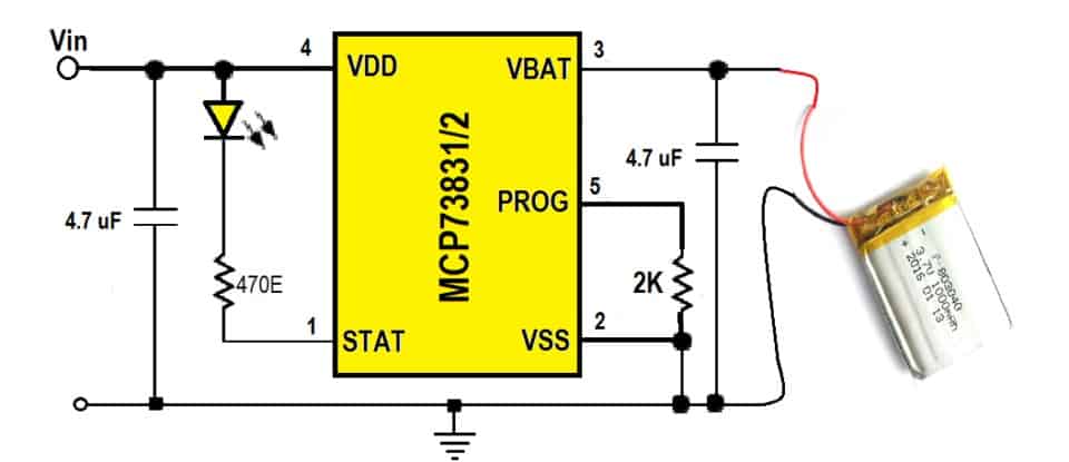
Li-ion battery charger circuit
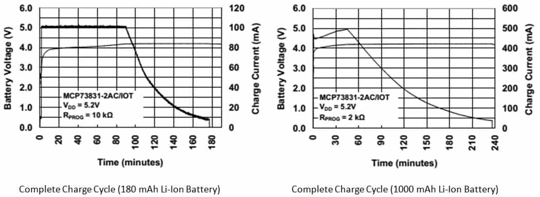
This article is about a tested example circuit for a Li-Ion battery charger that can be used to charge any 3.7V, 500mA Li-Ion battery from a 5V DC (USB, solar panel, DC adapter) source. This circuit is designed using Microchip MCP73831/2 IC. The MCP73831 is a highly advanced linear charge management controller for space-constrained, cost-sensitive applications. The IC uses a constant current/constant voltage charging algorithm with optional pre-regulation and charge termination.
So let's take a look at the MCP73831 IC and its features and implementation. It is also known as a micro-cell, fully integrated Li-ion Li-polymer charge management controller.
Features of the MCP73831
Let's discuss the characteristics of the MCP73831 Li-Ion/Li-Polymer Charger 4.2V, 500mA. Its characteristics are as follows:
Linear Charge Management Controller:
01. Linear charge management controller:
– Integrated pass transistor
– Integrated current sensing
– Reverse discharge protection
02. High precision preset voltage adjustment: + 0.75%
03. Four voltage adjustment options: 4.20V, 4.35V, 4.40V, 4.50V
04. Programmable charging current: 15 mA to 500 mA
05. Constant current and constant voltage charging algorithm, optional pre-regulation charging termination.
06. Optional charge end control: 5%, 7.5%, 10% or 20%
07. Constant current value can be set by 1 external resistor.
08. Automatic power-off: Under high power and high ambient conditions, limit the charging current according to the chip temperature.
09. Thermal regulation: Optimizing charging cycle time to maintain device reliability
10. Temperature range: -40°C to +85°C
11. Package:
– 8-pin, 2mm x 3mm DFN
– 5-pin, SOT-23
Applications of MCP73831
The MCP73831 has a wide range of applications in small portable devices due to its tiny size and optimal battery management capabilities. Some of the devices where it is widely used are:
1. Li-ion/Li-polymer battery charger
2. Personal Data Assistant
3. Mobile phone
4. Digital camera
5. MP3 player
6. Bluetooth headset
7. USB charger
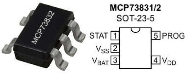
MCP73831 pin description
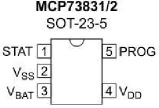
1. Charge status output (STAT)
The STAT output is used to connect to an LED for charging status indication. Alternatively, a pull-up resistor can be applied to a host microcontroller. STAT is a three-state logic output on the MCP73831 and an open-drain output on the MCP73832.
2. Battery Management 0V Reference (VSS)
Connect to negative terminal of battery and input power.
3. Battery charging control output (VBAT)
Connect to the positive terminal of the battery. Drain terminal of the internal P-channel MOSFET pass transistor. Bypass to VSS with a capacitor of at least 4.7 µF to ensure loop stability when the battery is disconnected.
4. Battery management input power supply (VDD)
A supply voltage of [VREG(Typical) + 0.3V] to 6V is recommended. Bypass to VSS with a minimum of 4.7 µF.
5. Current regulation setting (PROG)
Preregulation, fast charge and termination currents are adjusted by placing a resistor between PROG and VSS. Allowing the PROG input to float disables the charge management controller.
Design a 3.7 V, 500 mA Li-Ion Battery Charger Circuit
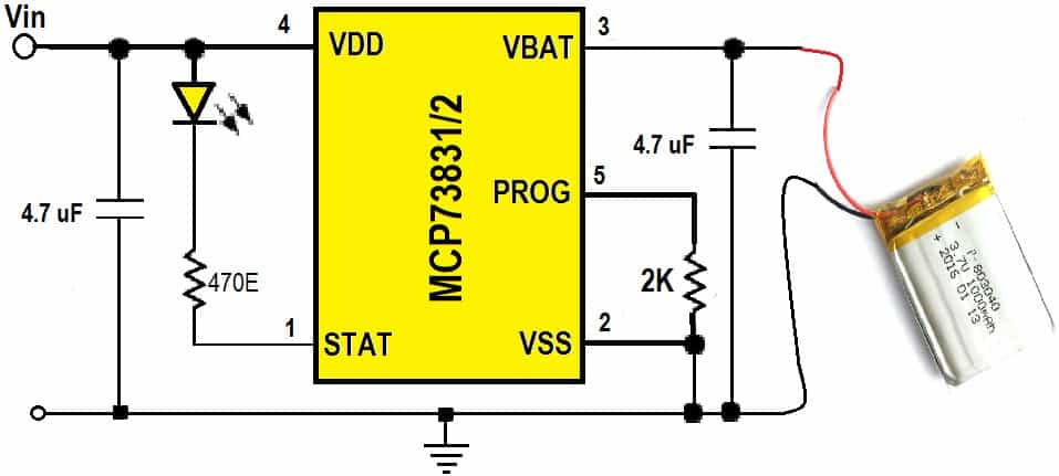
This is the smallest small Li-Ion/Li-Polymer charger that is so handy you can throw it in any project box. It's also very easy to use. Simply plug the input contacts into any USB port or any 5V DC power source and plug a 3.7V/4.2V Li-Polymer or Li-Ion rechargeable battery into the output plug on the other end.
Lithium-ion batteries need to be charged in a carefully controlled constant-current/constant-voltage (CV-CC) mode unique to this battery chemistry. Overcharging and mishandling of Li-Ion batteries can cause permanent damage, instability and potential danger!
Charging takes place in three stages: first a pre-charge, then a constant current fast charge, and finally a constant voltage trickle charge to keep the battery fully charged. The default charging current is 100mA, so it works with any size battery and USB port. If you wish, you can easily change it to 500mA mode by soldering the jumper on the back of the closure, as when you are only charging 500mAh or larger batteries.