Types of Transistors
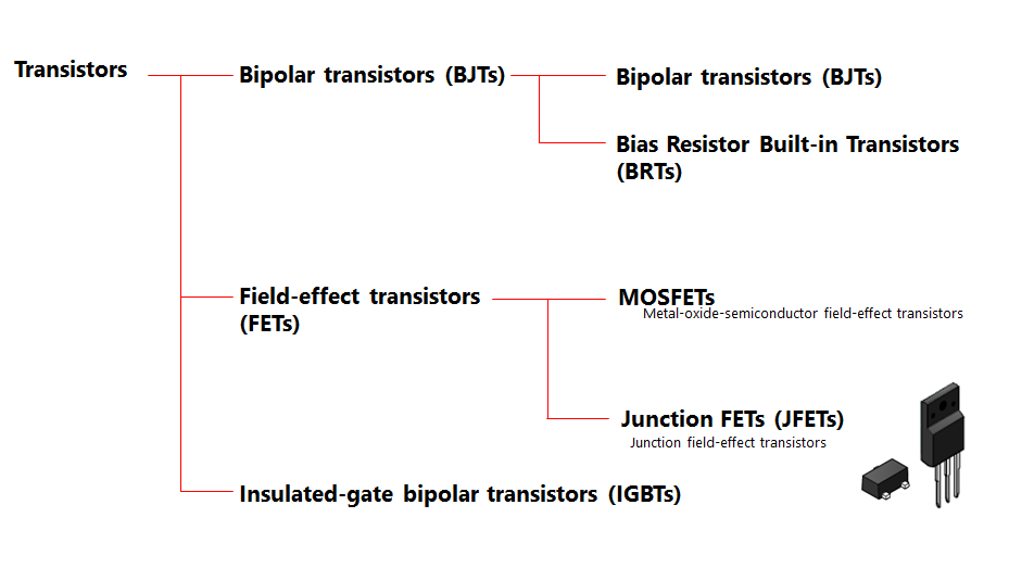
There are three broad types of transistors: bipolar, field effect, and insulated gate bipolar. Bipolar transistors are current-driven devices. Field effect transistors (FETs) and insulated gate bipolar transistors (IGBTs) are voltage drivers.
There are two types of bipolar transistors: NPN type and PNP type, and the NPN type covers low withstand voltage to high withstand voltage products. PNP type products with an withstand voltage of 400V or less, especially those with an withstand voltage of 200V or less, are the mainstream products. They have an amplification function to convert small signals into large signals. The ratio of the collector current I(C) to the base current I(B) (I(C)/I(B)) is called the DC current gain and is expressed as h(FE). When a small current (I(B)) flows from the base to the emitter, the current I(C) of I(B) × h(FE) flows from the collector to the emitter.
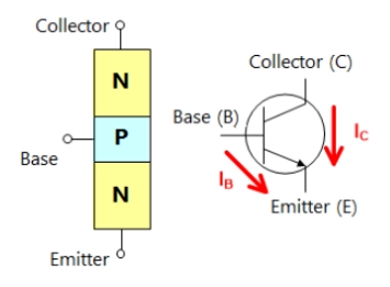
Symbols and structures of NPN transistors
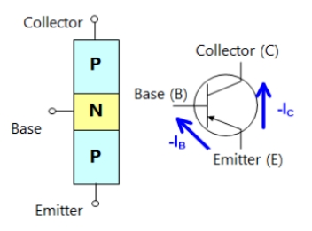
Symbols and structures of PNP transistors
The BJT is a current driver device driven by the base current.
Operation of NPN transistors
Base current: Current from base to emitter
Collector current: Current from collector to emitter
Operation of PNP transistor
Base current: Current from emitter to base
Collector current: Current from emitter to collector
Built-in bias resistor type transistor (BRT)
A BRT is a transistor with a built-in bias resistor, and a BJT is usually used in conjunction with a resistor in an electronic device. Using a BRT (integrated transistor and resistor) reduces the mounting area.

Example of BJT application Equivalent circuit of BRT
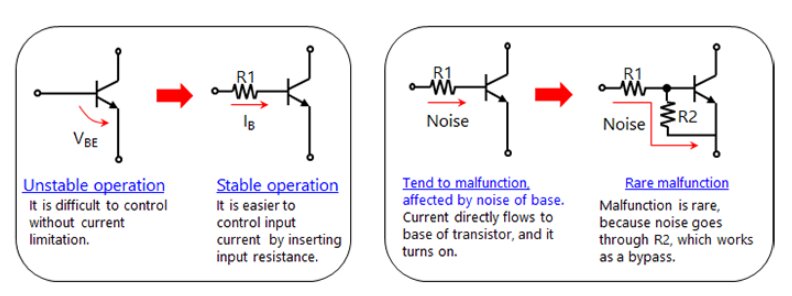
Why the basic circuit of a BJT needs resistors
Junction Field Effect Transistor (JFET)
JFET: Junction Field Effect Transistor
(1) In an N-channel junction-type field effect transistor (Fig. 3-1), electrons flow from the source to the drain when a voltage is applied between the drain and the source.
(2) When a reverse bias voltage is applied between the gate and the source, the depletion layer expands and inhibits the electron flow in (1). (Narrowing the path of electron flow)
(3) If the reverse bias voltage between the gate and the source is further increased, the depletion layer blocks the channel and electron flow stops.
As shown above, the voltage applied between the gate and the source controls the state between the drain and the source. So field effect transistors are voltage driven devices.
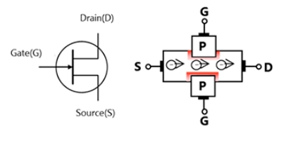
Fig. 3-1 Symbols and operation of N-channel JFETs
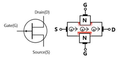
Fig. 3-2 Symbols and operation of P-channel JFETs
Metal Oxide Semiconductor Field Effect Transistor (MOSFET)
Metal oxide semiconductor field effect transistors (MOSFETs) are the most popular transistors today. there are two types of MOSFETs: N-channel (see Figure 4-1 below for N-channel) and P-channel (see Figure 4-2 below for P-channel). the N-channel is widely used in AC/DC power supplies, DC/DC converters, inverter devices, and so on, whereas the P-channel is used for load switches, high side switching, etc. The differences between bipolar transistors and MOSFETs are shown in Table 3-1.
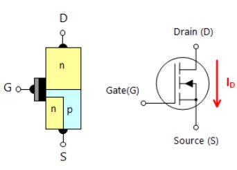
Fig. 4-1 Symbols and operation of N-channel MOSFETs
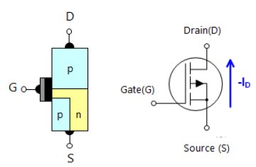
Fig. 4-2 Symbols and operation of P-channel MOSFETs
Insulated Gate Bipolar Transistor (IGBT)
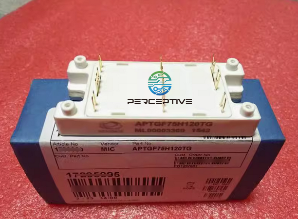
An IGBT is a device suitable for high current control with a voltage-driven MOSFET in the front stage and a transistor in the back stage that allows high current flow.
The equivalent circuit of an IGBT is shown in Figure 5-2. Set the RBE value so that the NPN Tr will not conduct.
Apply a conduction signal to the N-channel MOSFET gate to turn on the conduction state.
Current flows from the emitter to the base of the PNP Tr. This base current reduces the N-channel MOSFET.(conductivity modulation effect)
[Comparison with MOSFET].
The gate driver operation is the same as that of an N-channel MOSFET.
In the on-state, the reduced on-resistance of the N-channel MOS enables large currents.
The voltage drop from the PNP Tr emitter to the base occurs over the entire current region (adding up to approximately 1.0V as the on-state voltage).
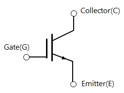
Fig. 5-1 Symbols of IGBT
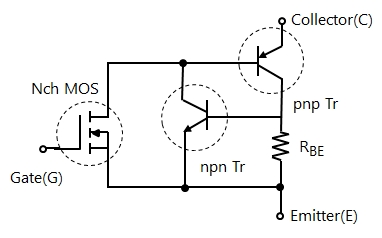
Fig. 5-2 Internal Equivalent Circuit of IGBT
Principle of Operation of Insulated Gate Bipolar Transistor (IGBT)
The operation of an IGBT connected as shown in Figure 6-1 is shown below.
(1) Applying a positive voltage to the gate will form an inversion layer in the P layer below the gate. The N-channel MOSFET in Figure 6-2 conducts as a conventional N-channel MOSFET.
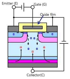
Fig. 6-1 Operation of IGBTs
(2) When the N-channel MOSFET is in conduction , the collector potential is positive. As a result, holes will be injected from P+ to N- through N+, and this injection accelerates the injection of emitter electrons.
(3) As a result, the increase in carriers (electrons and holes) reduces the N-layer resistance, which is normally high (conductance modulation effect).
As a result, the on-resistance of the N-channel MOSFET becomes lower, as shown in Fig. 3-14(b). -
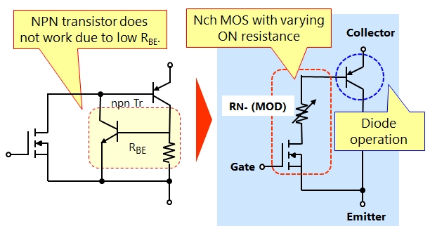
Fig. 6-2 IGBT Equivalent Circuit and Practical Operation Image
Gate Injection Enhancement Transistor: IEGT
In high-voltage IGBTs, it is difficult to obtain low V(CE(sat)) characteristics because of the low carrier concentration in the emitter-side drift layer (n-type layer).
IEGT development for obtaining low V(CE(sat)) performance at high withstand voltages (typically 1200 V or higher)
Figure 7 shows the structure and principle of the IEGT.
It has a trench gate structure. Pulling out the gate electrode will thin it. The result causes carriers to collect directly below the thin gate electrode, which increases the carrier concentration on the emitter side
The high carrier density reduces the resistance of the drift layer, resulting in a lower V(CE(sat))
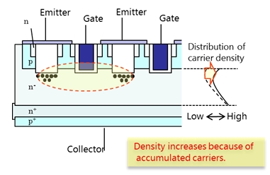
Fig. 7 Structure and carrier density of IEGTs
Applications of IGBTs
IGBTs are suitable for applications with simple drive circuits and high currents. They are currently used in soft-switching IH (induction heating) equipment up to 50 kHz, household appliances, vehicles and various AC drive applications. In the future, their field of application is expected to expand to various AC drive applications.
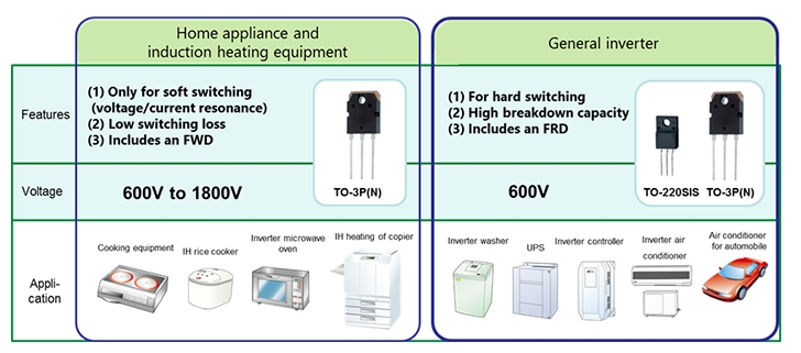
Fig. 8 Typical Applications of IGBTs
Note: IGBTs are not suitable for high-speed switching compared to MOSFETs due to bipolar operation.
Comparison of Forward Characteristics of IGBTs and MOSFETs
This paper compares the forward characteristics of MOSFETs (D-MOS) and IGBTs at voltages from 500 to 600 V. In the low current region, the MOSFET voltage drop is small, which is an advantage. The IGBT, on the other hand, has better forward voltage characteristics than the MOSFET in the high-current region, as shown in Figure 3-17. The performance difference between IGBT and MOSFET increases with increasing temperature due to the strong positive dependence of the forward characteristics of MOSFET on temperature.
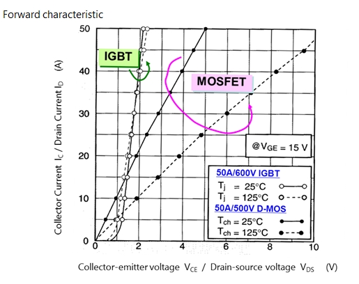
Comparison of Forward Characteristics of MOSFETs and IGBTs
The figure compares medium- and high-voltage products. In the operating current region, the on-resistance of low-voltage MOSFETs (e.g., trench MOSFETs) is much lower than that of IGBTs.
Given these characteristics and switching performance:
MOSFETs should be used for low current densities and switching power supply operation at approximately 100 kHz.
IGBTs should be used for high current density and AC drive operation up to 20kHz.
Here's a short video on transistors:
If you're interested in the content, pilease click on our website: perceptive-ic.com.

